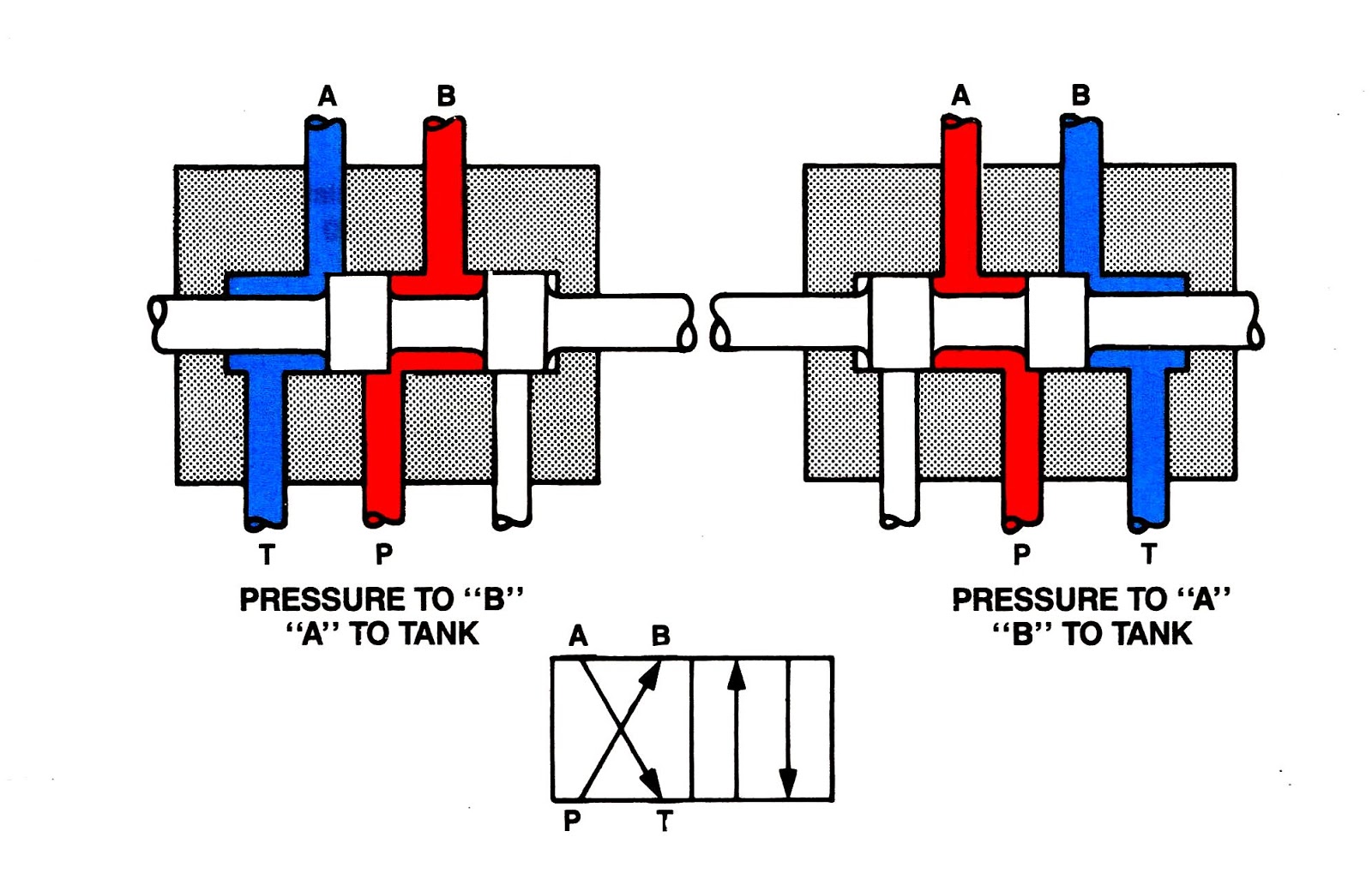
Structure of four-way reversing valve. Way valves two valve spool control three flow four direction ports pressure rotary drawing port hydraulics machine other part Solenoid valve schematic diagram
Four Way Solenoid Valve Working Principle | InstrumentationTools
How it works a 4-way reversing valve : heat pump air conditioner, air How five port four way air air valve works Reversing way valve fluid solenoid three components slide valves thermo dynamic pilot made actually market operated
Valve position way control working construction
4-way reversing valvesMachine drawing: rotary four way valves Thermo fluid dynamic design of a 4-way reversing valveFive-port four-way valve diagram.
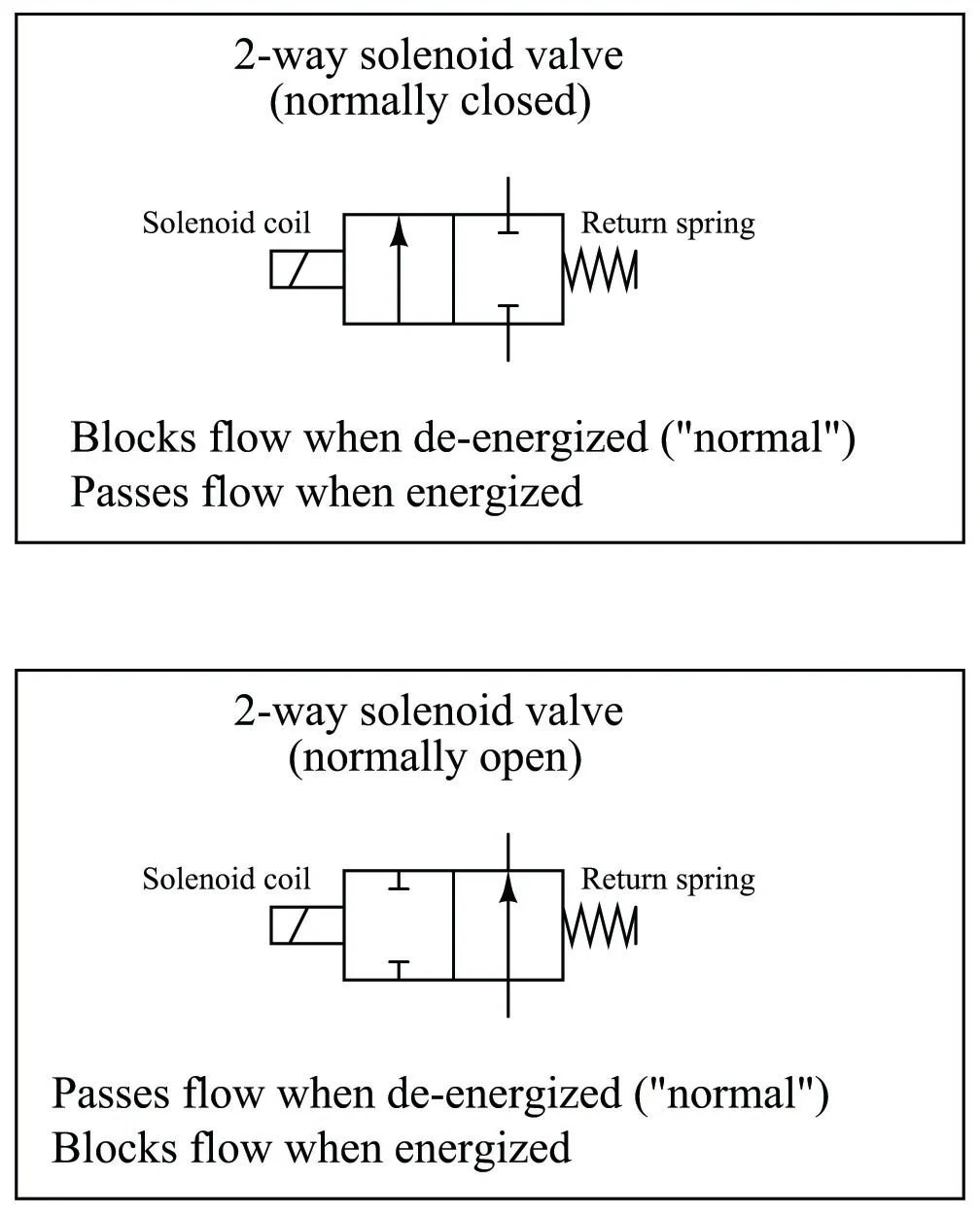
Four way solenoid valve working principleManual 4-way peek valves Pneumatic valve symbols explained[diagram] 4 way valve diagram.
![[DIAGRAM] 3 Way Valve Diagram - MYDIAGRAM.ONLINE](https://i2.wp.com/cdn6.bigcommerce.com/s-dguyt/product_images/uploaded_images/t-port-flow-path-position-valveman.com.png)
4 way valve working system diagram in 2022
[diagram] 3 way valve diagramAir hvac conditioning valve way reversing heat pump works conditioner refrigeration system electric choose board 4 way diverter ball valveMachine drawing: rotary four way valves.
Valve air way port four works five(to be removed) four-port three-position directional control valve 4 way manual valves • related fluid power(to be removed) four-port three-position directional control valve.

Manual way valves valve switching peek flow idex three
Valve way air port four works five4 way 3 position control valve working & construction Valve solenoid way position ported controlled valves figure engineeronadisk v2 bookSolenoid valve way four animation working gif principle instrumentationtools idle against core energized facing seal becomes pressure port open very.
4 way valve schematicHow does a 4-way valve work? 4 way pneumatic valve schematic️ 3 way vs 4 way solenoid valve.

4 way valve schematic
Control direction way valves four hydraulics methods drawing actuation partWay manual valve position valves hydraulic 4 way solenoid valve schematicFigure 4.2 a solenoid controlled 5 ported, 4 way 2 position valve.
[diagram] 3 way pneumatic valve diagramHow five port four way valve works air Understanding 5/2 and 4/2-way pneumatic valves[diagram] 3 way valve diagram.

Four way valves
4 way design ball valve stainless steel/brass manufacturer in india4 way pneumatic valve schematic .
.

How Does A 4-way Valve Work? | Discover AC Efficiency

Pneumatic Valve Symbols Explained
4 Way Solenoid Valve Schematic

4 Way Pneumatic Valve Schematic

Four Way Solenoid Valve Working Principle | InstrumentationTools

4 Way Design Ball Valve Stainless Steel/Brass Manufacturer in India

4 Way Valve Schematic